Next Generation PCB Design Constraint Management
New design systems support multiple users and concurrent rules – and they automate repeat tasks and use net topology templates – to reduce the time needed to complete complex designs.
As systems become more complex, the need to control physical routing and electrical elements is growing to such an extent that constraint entry is firmly on the critical path of the design process. Electronic system capabilities have exploded over the past two decades. In order to meet the growing needs of the consumer, the latest “gadgets” are required to carry out more data processing than ever before. This is true whether it is for graphics manipulation or Internet data downloads; the urgent need is to process more data in an ever shorter time frame. The consequence for the design team is that to achieve these data rates, the majority of the nets on a design are no longer simple connections from point A to point B. They have instead become signal propagation paths that can affect the quality of the signal directly.
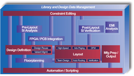
This has led to an increased focus on the high-speed aspects of the design, not only in the classic signal integrity requirements but also timing. To combat this problem the design team has had to take into consideration, and therefore need to control, the effects of the board stackup, routing, placement, etc. for the design. These new rules or constraints have to be encapsulated in the design requirements. The old maxim of “make it as short as possible” was okay when a design had a handful of critical nets, but when a design has 4,000 nets that all have to be considered for high-speed there’s a major issue. Figure 1 diagrams the library and design data management system. The constraint management system must be integrated with all the tools available for the design process, and be readily available to all users at any point to ensure that the rules are followed and that the design works properly.
|
|
Evolution of Rules
The need to control every aspect of the design has not always been the norm. For example, 20 years ago the majority of designs contained only a handful of nets that could be considered sensitive to layout, and these were mainly confined to the clocks, RF or analog content. The usual solution was for the engineer to sit with the layout designer and guide them step-by-step. Although this was very user intensive, the associated risks were low because such a small proportion of the PCB had to be treated this way. As time has progressed and the number of nets that require control has grown, design teams have to address the issue of specifying rules quickly and easily and then passing them to the layout designer. It is just not cost effective to have a digital engineer sitting with the layout designer while they lay out sensitive areas of a design that can take as many as eight weeks to complete.
The next stage in the evolutionary path was the engineer committing the rules to paper and passing them to the layout designer. These rules ranged from simply stating a net name and a general requirement to more detailed constraints. This process was used for quite some time.
As designs became more complex, it became increasingly difficult to convey the design intent to the layout engineer using bits of paper. In response, ECAD companies created functionality that would allow the design team to enter the same rules directly into the CAD system and then check against them. The immediate impact was that checking time was reduced; previously the designer would have to report all net lengths for the individual nets and then, with a calculator, make sure that they matched.
The move to using rule entry in CAD systems did not happen overnight, but was a gradual transition as the number of constraints increased. In many cases the systems were not intuitive, and for the casual user they had to be re-learned each time. The engineer may have only entered rules once every six months, while the PCB engineer would have to add rules to almost every design they undertook. The “track width and clearance” rule entry had traditionally been the domain of the PCB designer so it was inevitable that these new rules would be seen as an extension to their existing skill set.
Who Enters the Rules?
But interchange led to a dilemma. Engineers actually define the rules but they are not familiar with the entry system, while layout engineers are familiar with the entry system but do not define the rules. Passing the rules on a piece of paper was fine when the number of rules was small, but as the number of rules increased this system became slow and prone to error.
About this time new additional requirements were being added. No longer could the designer be content with simply controlling the length of a net, but signal quality was becoming an issue. Today, many nets are required to be constrained electrically as well as physically. Undershoot and overshoot, together with crosstalk, have a profound effect on signal timing. The designer may have routed the nets to the required length, but that does not always guarantee that the net performs electrically.
The constraints were no longer required to control just the track width and clearance but were becoming a central part of the design. Figure 2 shows the need to have access to the constraints during the complete design process. From the initial concept through verification, the design is constantly checked against some level of rule data.
|
|
With the increase in electrical requirements, there was an overwhelming need for a simple system that allowed the designer to capture the traditional physical high-speed rules and newly emerging electrical requirements in a single, easy to use environment. It was also preferable to amalgamate the broad spectrum of high-speed rules with the “track and gap” rules, thus providing a single point of entry using one consistent approach.
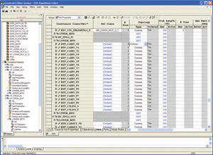
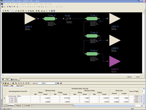
An ideal method to enter and display the constraints has proven to be a spreadsheet since many designers are accustomed to using them everyday. Using the simple approach of displaying the nets and constraints in rows and columns, the designer is presented with an intuitive interface. But engineers require more than just an entry system. They also need to be able to see if their constraints have been met. The display of the actual design value provides the user with immediate feedback to the status of the design using simple color coding. The actual values should be reviewed during the routing stage or as part of the signal integrity analysis verification step. In Figure 3 a tight integration with the high-speed analysis tools allows the designer to quickly determine the signal quality pre- and post-route.
|
|
Apart from being easy to use, the constraint system must be flexible enough to allow the designer to add rules in a variety of ways. The designer should be able to quickly define the topology or net break-up, whether it is from a standard set such as T-Shape, H-Tree or Star – that is automatically balanced by the router – through to a fully customized net order. Once defined, the user should be able to add the necessary constraints to the net or just between the pin pairs on the net.
With today’s memory busses there is a growing need to be able to add rules that reference other nets, or a subsection of nets in a design. Let’s consider the relationship between a data bus and its relevant clock net. The exact timing of the data bus may not be extremely important, but for the system to function it does require that the clock arrive some time after the data to allow the setup and hold time to be met. In this situation the user must be able to simply add a rule that states the clock net has a minimum length equal to the maximum length of the data bus, plus some additional timing margin. To further aid the rules entry, the ability to group nets together hierarchically not only allows the user to organize related nets but also enables the user to enter the constraints at the top level so that they will propagate down, speeding up the process.
Constraint Entry in the Critical Path
With the increasing number of constraints to be added to a design, the time taken to do so has also increased. Constraint entry has become a large portion of the design time, and the need to take the constraint entry off of the critical path has become of paramount importance. In an effort to reduce the overall design cycle time, there have been additional requirements placed on the constraint system. Some of the requirements are as follows:
- Automate repeated tasks
- Support for standard protocols such as DDR2 and PCI-X
- Net topology templates
- The need to have multiple users enter the rules simultaneously
There is a need within any constraint definition tool to make repeated tasks a standard operation where possible. One such example is the assignment of differential pairs. Many companies use naming conventions for differential pairs with either a suffix or prefix that designates their polarity, i.e. <net_name>_P and <net_name>_N. By simply allowing the user the ability to quickly associate the relevant pair together in the design greatly speeds up the process. In the past this has been a manually intensive process requiring the PCB designer to effectively provide the pairings. For a backplane manufacturer this is a very time consuming chore, especially considering that the board may have 500+ differential pairs. This process, which may have taken a few hours in the past, has been reduced to seconds with the added benefit of reducing the opportunity for errors in pairing the wrong nets.
A Mixture of Systems
In an effort to decrease the design cycle times, PCB systems are becoming a mixture of standard, off-the-shelf protocols such as DDR, PC-X and custom/in-house developed systems. For many companies their value-add is the unique feature that their system offers. This mixture of design techniques requires different approaches to entering the constraints.
When using a DDRAM DIMM, each manufacturer generally provides an extensive layout guide that ensures the system functions properly. The silicon vendors’ rules are normally length based and the user implements these through the constraint system to drive PCB routing.
The routing constraints for the remaining circuitry are normally developed with the aid of signal integrity analysis. The net should be extracted directly from the constraints system and passed to the SI tool where the designer typically investigates the effects of different topologies and sweeps combinations of track lengths to ensure that the system functions as specified. Once the net parameters have been determined they should be saved as a topology template, which can then be applied to an individual or group of nets in the original design. As can be seen, the tight integration between this “what if” analysis environment and the constraints system is an essential part of the solution.
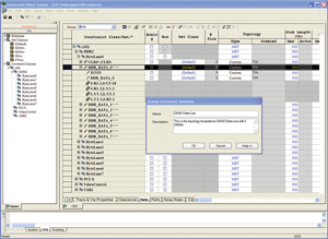
Topology templates can also be created from an example net in the design. In the case of DDR2 the designer could simply configure one token net, such as a single data line, and then create the topology template from this net. Once created it is a simple matter to apply it to the remaining data nets. Any template can also be saved to a library so that they can be used in other designs, but this makes obvious sense for standard protocols. The use of topology templates, whether they are design specific or from a library, greatly reduces the time taken to enter a set of constraints to multiple nets. Figure 4 shows a topology template that can be quickly created from a specimen net to be applied to other nets in the design.
|
|
The trend is that the design team must squeeze more and more functionality in the product with less and less time to do it. With this continued pressure, the design team must find solutions to the problem. Board layout, once a serial process, has steadily moved to a parallel or concurrent approach. In many situations the PCB designer begins the layout before the schematic is 100% complete, focusing on stable sections of the design or perhaps running feasibility studies for routing.
Rules-Collaboration
With the specialist knowledge required for some sections of the designs, it is not uncommon to have an individual engineer concentrate on one distinct area of the PCB, such as the PCI bus or DDR2. They are responsible for not only the connectivity, but also the constraints. The process of multiple users editing different connected sheets together has been around for a long time, but the ability to have multiple engineers editing the constraints has not generally been supported. With the constraint entry task firmly on the critical path there needs to be a shift to allow multiple users to edit the data concurrently.
Some companies have tried to address this problem by creating multiple copies of the constraint data, one copy for each engineer. These copies are then edited and, at an appropriate moment when everyone is ready, they are somehow merged together. This, as always, is fraught with danger. The constraints can be quite dynamic when there are multiple engineers, a layout designer and a SI specialist all editing the design concurrently.
To provide a truly concurrent constraint entry system each user must be able to enter their rules freely while viewing the complete rule database. The system should obviously provide feedback to users so that they can see in real-time all data edits made by the other designers. If a designer is editing a specific cell the other designers should be locked out of that cell, but to help manage the interactions, they should be able to see who is performing the edit. Likewise, cells that have been edited previously should be highlighted so that all users are aware they could be overwriting existing edits. This approach provides a leap forward in the constraints entry process; no duplication of data, no individual updates made without the full design context and no merging.
Companies now have to give greater consideration to the rules entry process and can no longer trust the old methods that have become inefficient and error prone as the number of requirements has increased. However, this situation will not improve since with each new design technology, the number and complexity of the rules increases, thus keeping constraint entry at the forefront. An easy-to-use system coupled with the ability to automate the constraint entry definitely makes the tool accessible to the casual user and improves the overall process, but the ability to have true concurrent rules definition by multiple disciplines will result in the drastic time reductions needed in the rules entry process. PCD&M
Andy Critcher is a product architect at Mentor Graphics Corp. He can be reached at This email address is being protected from spambots. You need JavaScript enabled to view it..


