Laminate Material Selection for RoHS Assembly, Parts 1 and 2
Success in lead-free assembly is based on matching critical laminate properties with the design constraints.
Ed. - Part 1 was published in the November issue of PCD&M. Part 2 was published in the December issue. Both parts are included here.The RoHS deadline has come and gone. Success in preparation for this deadline has varied greatly. For some, it was a relatively seamless transition. For others, it could not have been more painful. And for those with exemptions that continue over the next few years, there is still a great deal of work to be done. The segments that currently have exemptions are generally the more complex applications where product reliability is most critical. In addition, these segments are facing pressure to comply ahead of the deadlines due to component availability issues and constraints within the EMS industry. These ongoing transitions will be the most challenging in terms of base material selection and qualification due to the designs of the PCBs, the complexity of assembly, and the requirements for long-term reliability and electrical performance.
From the standpoint of compliance, most laminate materials are acceptable. Most materials do not contain lead or the other restricted metals. The brominated flame retardant used in most laminates is not a restricted material. However, in terms of compatibility, the answer is very complex. This is the result of several factors. First, PCB design and construction will have a significant impact on the base material properties required. Thin, low layer count PCBs have different requirements when compared to thick, high layer count PCBs. Copper weights, aspect ratios and other design features will also have an impact. End use application and the associated requirement for long-term reliability and electrical performance will impact the decision-making process as well. The requirements for a cell phone, video game or even a computer motherboard will be very different than those for high-end servers, telecommunications gear, avionics, and critical medical and automotive electronics. Last, not all lead-free assembly processes are the same. Some designs will experience peak temperatures of around 245°C while others will experience peak temperatures of up to 260°C, or even higher in a few cases. Some boards may experience 2-3 thermal cycles, others up to 5-6, and more depending on how many reworks are allowed. All of this makes it impossible to recommend one base material for all applications without either under specifying the laminate material and risking defects during assembly or later on in the field, or over specifying the material and paying too much for the material or limiting availability.
A very critical point that must be emphasized with respect to these issues is that laminate manufacturers can easily make improvements in one property, but often this can adversely affect other important properties. For example, it is relatively easy to formulate a resin system with a very high time to delaminate in conventional T260 or T288 tests, or to engineer a resin system with a very high decomposition temperature. However, this is often achieved at the expense of other (i.e. mechanical) properties and may make the material more difficult to use successfully in conventional PCB manufacturing processes without sacrificing design flexibility. Therefore, achieving the best balance of properties to meet the needs of the OEM, EMS and PCB manufacturer is absolutely critical.
Critical Laminate Properties
The higher temperatures of lead-free assembly have an impact on each of the three main components of laminate materials, the resin system, the glass cloth and the copper foil. Table 1 [PDF format] summarizes the key issues for each of these main components.
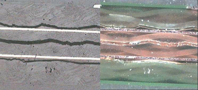
Substantial work describing the impact of lead-free assembly temperatures on the base materials and finished PCBs has been gathered recently1,2,3,4,5. These works have identified the critical base material properties that must be considered when selecting a material for lead-free assembly applications, and therefore, only a summary is provided in Table 2 [PDF format]. Figure 1 is now a well-known example of what can happen when the wrong choice of base material is made. This is a cross-section of a relatively simple 4-layer board that used a conventional high-Tg FR-4 and was then processed through lead-free assembly with a peak temperature of 260°C. In this PCB, delamination occurred at the resin-to-internal copper interface as well as the resin-to-glass interface. However, even if a PCB survives assembly without defects, a second key question is, has long-term reliability of the PCB been compromised? For the currently exempt product segments yet to be transitioned to lead-free assembly, this is an even more critical issue.
|
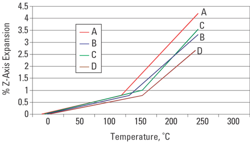
The historical focus on Tg is probably the result of its effect on total Z-axis expansion. However, because of differences in CTE values, even the relationship between Tg and thermal expansion requires further analysis. Figure 2 illustrates the relationship between Tg and thermal expansion for the products in Table 3 [PDF format]
|
Products with the same CTE values (A & C for example; note that above Tg the lines are parallel) will differ in total expansion based on their Tg values (Figure 2). For example, the conventional 175°C Tg material (C) exhibits less total expansion than the conventional 140°C Tg material (A) because the onset of the higher post-Tg rate of expansion is delayed by 35°C. However, the 175°C material with a lower CTE value (D) exhibits much less total expansion than the conventional 175°C Tg material even though the Tg values are the same. Furthermore, the 150°C Tg material with reduced CTE values (B) exhibits approximately the same total expansion (3.4%) as the conventional 175°C Tg material (3.5%). However, with a decomposition temperature that is significantly higher, this mid-Tg FR-4 material is much more compatible with lead-free assembly than the conventional 175°C Tg material. Knowing Tg and CTE are not enough.
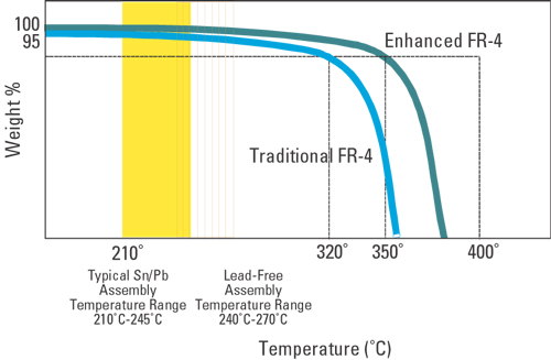
While glass transition temperature (Tg) and Z-axis expansion have been a focus of attention over the years, only with the introduction of lead-free assembly has the decomposition temperature (Td) gained significant attention. The decomposition temperature has always been important in terms of reliability, but most people have used Tg as a proxy for material reliability in the days of leaded solder. One reason for this is that other things being equal, a higher-Tg will result in less total thermal expansion, and therefore less stress on plated vias. What wasn’t discussed is that it is common for conventional high-Tg FR-4 materials to exhibit somewhat lower decomposition temperatures than conventional 140°C Tg FR-4 materials. This is highlighted by the fact that most conventional 140°C Tg FR-4 materials exhibit longer T260 times than conventional high-Tg FR-4 materials. To highlight the importance of Td, examine Figure 3.
|
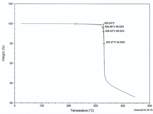
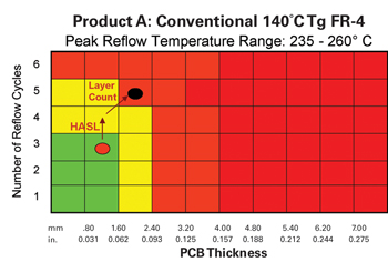
The traditional high-Tg FR-4 materials we have become familiar with have Td values in the range of 290-310°C. Traditional 140°C Tg FR-4 materials are generally somewhat higher, with a typical example of a material with a Td of 320°C shown in Figure 2. In the typical tin-lead assembly environment, peak temperatures do not reach the point where decomposition is significant for either the traditional or enhanced products. However, in the lead-free assembly environment, peak temperatures reach the point where a small, but significant level of decomposition can occur for the conventional materials, but not for the enhanced products. This seemingly small level of decomposition in the conventional products can have extremely significant effects on reliability, especially if multiple thermal cycles are experienced.
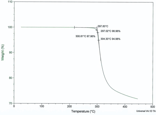
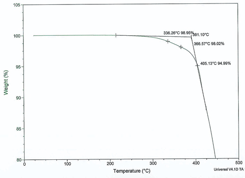
As long as the temperatures experienced during assembly and rework do not exceed the temperature at which decomposition begins, there may not be further benefit to higher decomposition temperatures. In addition, the resin system modifications often made to increase Td can often lead to other problems, such as brittleness or hardness of the resin system that negatively impacts PCB manufacturability, e.g. drilling, scoring and routing, or fracture toughness in tight pitch PTH areas. As not all lead-free compatible materials use the same resin systems, great care should be used in selecting a material that balances the requirements of the OEM, assembler and PCB fabricator. A simple review of a material data sheet or IPC slash sheet is not sufficient to guarantee success. Involvement with the base material supplier to fully understand the capabilities of a material and the required processing to be successful is even more important in lead-free applications. To expand on this, examine Figure 4, Figure 5 and Figure 6.
|
|
|
First, note the slope of the decomposition curve in Figure 6. By the 5% decomposition definition, this material has a Td of 405°C. However, if you look at 1% and 2% values, you get 336°C and 367°C, which are significantly lower than a reported 5% value of 405°C. This is not to say that a 1% Td of 336°C is bad. In fact, this material has exhibited exceptional reliability in lead-free applications. However, it does point to the need to understand decomposition levels other than the 5% level. In contrast, the material in Figure 5 has a 5% Td of 330°C with 1% and 2% Td’s of 326°C and 328°C, respectively. In this case, there is a very small difference between the 1%, 2% and 5% values, and this material has also proven to have excellent performance in a broad range of lead-free assembly applications.
Last, the standard high-Tg material in Figure 4 exhibits a 5% Td of 305°C with 1% and 2% values of 297°C and 301°C. This is also a small range of values, but in this case the absolute values are lower and begin to approach the range of temperatures that can be experienced, at least locally, in a board that undergoes lead-free assembly and rework. Materials such as this have not performed with adequate reliability to be considered for anything but the simplest of lead-free applications. If PCBs made with these materials are stored in uncontrolled environments and are allowed to absorb even a modest level of moisture, the combination of lower Td’s with the higher vapor pressure of water at lead-free temperatures can lead to catastrophic defects in assembly, or severely degraded long-term reliability.
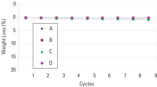
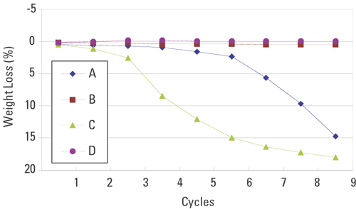
To take this a step further, examine the materials listed in Table 3. These are four FR-4 materials, with material C being the same material as shown if Figure 4, and material D being the same as the material in Figure 5. The impact of decomposition temperature when these materials are exposed to multiple thermal cycles to different peak temperatures is highlighted in Figure 7 and Figure 8. Figure 7 graphs cumulative weight loss (decomposition) for these materials when cycled repeatedly to a peak temperature of 235°C. Clearly, there is little impact on resin decomposition when the peak temperature reaches 235°C. Figure 8 presents the same results when the peak temperature is increased to 260°C. Obviously, the increase in temperature to 260°C has a severe impact on resin decomposition for the traditional FR-4 materials as they experience multiple thermal cycles, especially the conventional high-Tg material (product C). The rapid degradation in material C after only a few thermal cycles highlights why this material is not recommended for lead-free assembly applications. Indeed, as more data is gathered, thermal cycling seems to have a much greater impact than even one cycle to a very high temperature, even if it is for a long time.
|
|
Impact on Printed Circuit Reliability
In addition to the works already cited, there have been excellent studies recently on the impact of lead-free assembly specifically on PCB reliability6,7,8. These works present statistical analyses showing the impact of lead-free assembly on PCB reliability and reach important conclusions regarding the base materials. While there is not perfect agreement among all published works, the differences typically are the result of a different focus, e.g. whether the focus is on complex, thick PCBs with stringent reliability requirements vs. relatively less complex PCBs with shorter intended field lifetimes or less stringent reliability requirements.
Conclusions include:
- A minimum decomposition temperature is critical for lead-free assembly compatibility, although higher Td's are not always better. Trade-offs with other properties, e.g. manufacturability, fracture toughness, etc., make achieving the right balance of properties critical.
- Tg and CTE values are important because of the effects on thermal expansion, especially in thicker PCBs.
- Most conventional (dicyandiamide [dicy]-cured) high-Tg FR-4 materials are generally not compatible with lead-free assembly, or can only be used successfully in a very limited range of applications.
- Conventional 140°C Tg materials may still be suitable for PCB designs with limited thickness and reliability requirements, particularly when intermediate peak temperatures are used in assembly. This is largely the result of these materials having slightly higher decomposition temperatures than the higher-Tg equivalents.
- Mid-Tg FR-4 materials with high decomposition temperatures are viable products for many lead-free assembly applications involving intermediate-complexity PCB designs.
- Materials with a sufficiently high decomposition temperature, high-Tg and reduced CTE values are suitable for the broadest range of applications, including complex PCBs assembled at 260°C peak temperatures.
- Balancing material properties with PCB manufacturability is critical. Materials that exhibit excellent properties have failed because of difficulties experienced when fabricating the PCB, e.g. fracturing in drilling, routing or scoring, difficulty in texturing drilled holes for copper plating, resin recession or hole wall pull-away during thermal stress.
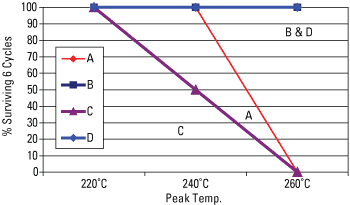
In order to highlight a couple of these conclusions, consider the following tests2. First, multilayer PCBs made from the materials in Table 3 were processed through IR reflow cycles at different peak temperatures. The PCB was a 10-layer, 0.093" (2.6mm) thick board "designed to fail," meaning the copper weights and patterns, construction and resin contents were chosen so that the board would be more sensitive to thermal cycles. In addition, the dwell time at the peak temperature was 1.5 minutes. This allowed differences in material performance to be detected more clearly. Figure 9 graphs the percentage of boards surviving six reflow cycles without any evidence of blisters, measles or delamination.
|
Notably, the first material to exhibit defects is the conventional high-Tg FR-4 material. This material began to exhibit defects when the peak temperature reached 240°C. At a peak temperature of 260°C, the conventional FR-4 materials, the 175°C Tg and the 140°C Tg products, all exhibited evidence of defects. On the other hand, the materials with higher decomposition temperatures, both the 150°C Tg and the 175°C Tg products all survived six cycles to 260°C.
In another test, three high-Tg materials were evaluated through IST testing. This particular test provided insight into the effect of thermal expansion and decomposition temperature on long-term reliability, as assessed by the IST method. The materials are shown in Table 4 [PDF format].
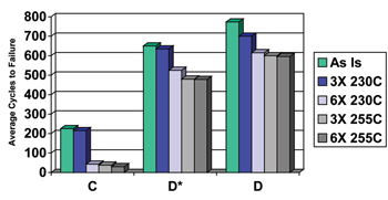
Note that the Tg values are the same, but differences exist in decomposition temperatures and thermal expansion values. Product D* is similar to Product D except that it has a higher level of thermal expansion. Product D* exhibits approximately the same thermal expansion as Product C, but Product D* has a higher decomposition temperature. Product D has both a high decomposition temperature and a very low level of thermal expansion. The PCB tested was a 14-layer, 0.120" (3.1mm) thick multilayer with 0.012" (0.30mm) diameter plated through-holes. The average copper plating in the via was 0.8 mils (20.3 microns), although 1.0 mil (25.4 microns) had been requested. Figure 10 charts the average number of cycles to failure (10% resistance change in the plated via net) at various levels of preconditioning to simulate assembly cycle exposure.
|
|
Clearly, the two materials with improved decomposition temperatures exhibit much better performance than the conventional high-Tg product. Also, in comparing Product D to Product D*, it appears that the lower thermal expansion of Product D does offer improvement in the number of cycles to failure, but this improvement is smaller in comparison to the improvement due to the higher decomposition temperature, at least for this board design. The benefit of reduced thermal expansion becomes more important as the thickness of the PCB increases. In addition, the technique used to reduce the CTE values also provides benefits in PCB manufacturability.
Understanding The Potential Impact On Electrical Performance
Most of the FR-4 laminate materials developed for lead-free assembly applications use an alternative resin chemistry in comparison to the conventional dicy-cured FR-4s. The most common alternatives are commonly referred to as "phenolic" or "novolac" cured materials. While there is some variation between these materials, as a group they tend to exhibit somewhat different electrical performance, particularly with respect to dielectric loss or Df (dissipation factor). For most applications operating in typical frequency ranges, the differences are not significant. However, as operating frequencies increase towards the higher end of FR-4 applications and impedance control becomes more critical, these differences can become very significant. Table 5 [PDF format] includes the same materials as Table 3, but also shows the differences in dielectric constant (Dk) and Df. It also includes a lead-free compatible material designed to improve Dk and Df performance in comparison to the phenolic lead-free compatible materials. Note that different types of measurement systems can result in different measured values for Dk and Df. Laminate resin contents and other factors will also influence these properties. So when examining Table 5, the comparisons between these materials are more important than the absolute values reported for each material. For these comparisons, the same measurement system and resin contents were used.
From this table it is clear that the improved phenolic FR-4 materials are not quite as good in terms of electrical performance in the range of 2-5 GHz as the conventional dicy-cured materials, particularly with respect to Df. However, material E exhibits thermal properties that are at least as good, if not better than even the improved materials discussed up to this point. In addition, the electrical performance of material E is even better than the conventional dicy-cured materials, especially in terms of Df performance. This non-dicy, non-phenolic material is now being evaluated for use in applications requiring not only lead-free compatibility, but also electrical performance superior to the phenolic materials that have been adopted in existing lead-free designs.
Selecting The Right Base Material For Your Application
A common question from PCB designers and fabricators, EMS companies and OEMs is whether a given material is compatible with lead-free assembly. While everyone is looking for a simple answer, the solution becomes complex because of the range of PCB designs (board thickness, layer counts, aspect ratios, via pitch, etc.) as well as the differences in lead-free assembly processes, e.g. the specific peak temperature and number of thermal cycles a board will experience. In addition, people will generally want to use the least expensive material that is suitable for a given application. So while it is easy to specify an advanced product for lead-free compatibility, the approach taken here is to balance cost and performance. In an attempt to simplify this discussion, a material selection tool has been developed which can be used to suggest what materials should be considered for a given application.
This tool is based on data such as that presented here and in the references, as well as empirical results from prototype and production experience with lead-free assembly applications. The experience of several people with 'hundreds of years' of combined experience has been leveraged in designing these tools. However, no such tool can address every specific application with 100% confidence. In addition, the capabilities of various PCB fabrication processes can also impact the performance of the finished board. So while these tools are based on considerable data and experiences from a number of sources, it is intended to serve as a general guide for typical applications, and it remains the user's responsibility to confirm acceptability of any material recommended. This is particularly true with respect to long-term reliability requirements. For example, the field reliability requirement for a cell phone PCB is going to be different than for a very complex high-end computer or telecommunications infrastructure PCB.
|
|
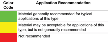
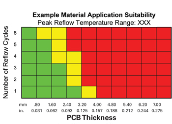
The intent in developing this tool was to come up with a simple method for dealing with the multitude of variables in PCB design and assembly. Figure 11 shows the basic color-coding selected for this. Figure 12 shows an example of the actual chart format. In the horizontal axis it divides PCBs into thickness categories and in the vertical axis it differentiates by number of reflow processes.
|
|
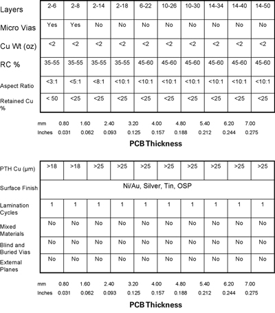
This format forces definition of a typical PCB design for each range of thickness shown on the X-axis. While this is very difficult and we realize that as soon as we attempt to define "typical" most people will be able to think of exceptions to the rules, these represent what we think are fair descriptions of a broad range of products. In addition, you will see that an attempt is made to define a procedure for accommodating the exceptions. Figure 13 outlines the typical features for PCBs in each thickness range in the charts.
|
|
|
|
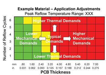
In order to accommodate the exceptions to these criteria, a method was developed to adjust the selection tool based on specific design features or processing conditions. The basic concept for these adjustments is shown in Figure 14, and the specific adjustments are shown in Figure 15 [PDF format].
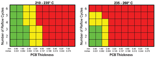
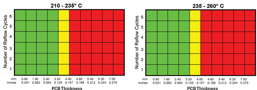
For the purposes of this article, we will present the charts for the materials discussed earlier and summarized in Table 5. However, this same information is available for other products, including low Dk/Df materials and halogen-free materials. Figure 16 shows the charts for product A with two different assembly temperature ranges, 210-235°C for tin-lead assembly and 235-260°C for lead-free assembly.
|
|
As you can see when these charts are presented side-by-side, the range of designs that this product is deemed suitable for decreases as the assembly temperature increases. This should be expected of course, based on the earlier discussion of material properties. The other key point is that there may still be a group of products, albeit more limited, where a standard 140°C Tg material may be adequate and the most cost effective option. This may help clarify some of the confusion we have heard about whether standard FR-4 materials are lead-free compatible or not. While we hate to give the answer "it depends," the truth is that for specific designs with specific requirements for reliability, the answer is "yes." For other designs, applications or reliability requirements, the answer is "no." The value of this tool is that it attempts to define the range of PCB designs where specific materials may be considered.
|
|
|
|
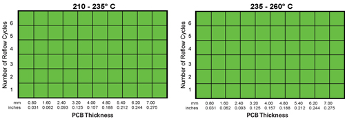
Figure 17 presents similar charts for product C, which is the higher-Tg conventional FR-4 material. This is where the conversation gets very complicated. From Table 5 you can see that the decomposition temperature for this product is 310°C, which is the lowest of the materials described. On the one hand, the higher-Tg of this product helps reduce the total amount of Z-axis expansion, and therefore stress on plated vias. On the other hand, the lower decomposition temperature makes this material the most sensitive to higher assembly temperatures. In fact, the range of 235°C to 260°C is a very broad temperature range for this product. Limited success may be seen when assembling at the low end of this range, but as temperatures increase, especially towards the high end of this range, we simply would not recommend that this product be considered, due to the potential for resin decomposition and resultant defects. Further, some of us would recommend that standard high-Tg FR-4 materials should not be considered at all for lead-free applications. Products B, D and E are significantly more robust in these applications and offer attractive cost-performance relationships. Extreme caution should be exercised if you are considering a conventional high-Tg FR-4 for a lead-free application, and we recommend that you discuss this with your laminate material supplier. In contrast, consider the charts for products B, D and E in Figures 18, 19 and 20, respectively.
|
|
|
|
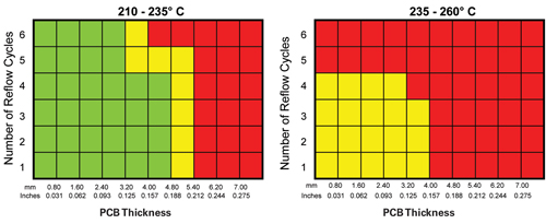
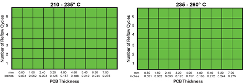
Product B, with a Tg of 150°C, is better suited for lead-free assembly than Product C with its 175°C Tg. This is due the fact that product B has a decomposition temperature approximately 25°C higher than product C. In addition, as shown in Figure 2, products B and C exhibit approximately the same total amount of thermal expansion in the range from 50°C to 260°C. You may notice that the charts for the different peak temperatures are shown to be the same for product B in Figure 18. This is partly due to the limited experience to date with this product in thick PCB designs. In addition, at lower peak temperatures, the number of reflow cycles that this product can withstand can go beyond six for thinner PCBs. If the two charts extended beyond six cycles, more differences would be seen.
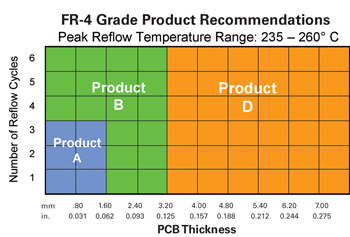
Product D, with a high decomposition temperature and very low level of thermal expansion, is suitable for the broadest range of applications (Figure 19). Product E offers not only a high decomposition temperature and very low thermal expansion, but also significantly improved electrical performance. Combining these recommendations allows us to make some general recommendations that also take material cost into consideration. Figure 21 summarizes the "cost vs. performance" recommendations for materials A through D in lead-free applications. Where improved electrical performance is required, product E should be considered.
|
|
Application of This Tool
A simple example helps illustrate the practical application of this tool. A customer presented us with a PCB design that was being converted to a lead-free assembly process. Some key features of the PCB as they relate to how it differed from a typical PCB as defined in Figure 13, and the recommended adjustments suggested, are shown in Table 6 [PDF format].
Figure 22 shows the results of making the adjustments suggested, and shows that this material is not recommended for this application. Figure 21 recommends that product B be used in this application, and empirical evidence has shown that when the standard 140°C Tg material was used, some level of assembly related defects were observed. When product B was used, no assembly related defects have been experienced.
|
|
The question of whether a given laminate material is compatible with lead-free assembly can be very complex due to the many variables in PCB design and manufacturing. In addition, there are variations in lead-free assembly processes as well. Specifically, peak temperatures, dwell times at peak temperatures, heat-up rates, cool-down rates, and rework processes can all vary and complicate this decision. As stated earlier, the temperature range from 235°C to 260°C is a critical range for laminate materials, and some materials may be moderately successful at the low end of this range, but fail at the higher end. Additional work investigating these assembly-related variables is underway. The existing tools for base material selection for lead-free assembly continue to be developed and improved as more data is collected and analyzed.
Critical base material properties with respect to lead-free assembly applications include:
- The decomposition temperature: Some minimum value is needed, but above this level, higher values are not always better.
- Thermal expansion properties: Improved materials have reduced levels of thermal expansion.
- Glass transition temperature: A higher glass transition temperature delays the onset of rapid thermal expansion and therefore reduces total expansion within a temperature range.
- Moisture absorption: In particular, if PCBs are stored in an uncontrolled or humid environment prior to assembly, drying of boards prior to assembly or selection of a material less prone to moisture related problems should be considered.
- Time to delamination: T260 and T288 values are a simple way to screen materials for compatibility with lead-free assembly. However, testing at higher temperatures or requiring excessive times may not be necessary.
Balancing these properties with the level of reliability required along with PCB manufacturability concerns is vital. PCD&M
Ed Kelley is director high reliability products at Isola Group; This email address is being protected from spambots. You need JavaScript enabled to view it.. Erik Bergum is director global marketing at Isola Group; This email address is being protected from spambots. You need JavaScript enabled to view it..
References
- Bergum, Erik, "Application of Thermal Analysis Techniques to Determine Performance of Base Materials Through Assembly," IPC Expo Technical Conference Proceedings, Spring 2003.
- Kelley, Edward, "An Assessment of the Impact of Lead-Free Assembly Processes on Base Material and PCB Reliability," IPC/Soldertec Conference, Amsterdam, June 2004.
- Hoevel. Dr. Bernd, "Resin Developments Targeting Lead-Free and Low Dk Requirements," EIPC Conference, 2005.
- Christiansen, Walter, Dave Shirrell, Beth Aguirre and Jeanine Wilkins, "Thermal Stability of Electrical Grade Laminates Based on Epoxy Resins," IPC Printed Circuits Expo, Anaheim, CA, Spring 2001.
- Kelley, Ed, Bergum, Erik, Humby, David, Hornsby, Ron, Varnell, William, "Lead-Free Assembly: Identifying Compatible Base Materials For Your Application," IPC/Apex Technical Conference, February 2006.
- Freda, Michael and Furlong, Jason, "Application of Reliability/Survival Statistics to Analyze Interconnect Stress Test Data to Make Life Predictions on Complex, Lead-Free Printed Circuit Assemblies," EPC2004, October 2004.
- Brist, Gary and Long, Gary, "Lead-Free Product Transition: Impact on printed Circuit Board Design and Material Selection," ECWC 10/APEX/IPC Conference, February 2005.
- Ehrler, Sylvia, "Compatibility of Epoxy-Based PCBs to Lead-Free Assembly," EIPC Winter Conference, 2005, & CircuiTree, June 2005.
