Algorithm for Constructing the Transient Process in a Meander Delay Line in PCBs
Analytical dependencies for calculating the efficient delay of signals at any predetermined level of receiver.
The technical and performance characteristics of computer systems depend largely on multilayer printed circuit board (PCB) design and manufacturing techniques. To take full advantage of speed performance of logic gates in the sub-nanosecond range, developers need to constantly improve methods for computer system design to ensure the integrity and consistency of the transmitted signals, including the use of meander structures. Use of a higher frequency band has led to the occurrence of the new physical causes of signal destruction such as interference, skin effect, dielectric losses, etc. The signal front phase dispersion has become the main time response characteristic of interfaces. Particularly, this requirement is critical for paraphrase transmission. The printed meander-type delay lines are a precision tool for such dispersion compensation.
To save space, printed delay lines are implemented in the form of meander (serpentine) lines. In turn, the electromagnetic coupling between the adjacent sections causes the pulse distortion, and, consequently, this results in the occurrence of the total delay augmentation effect in transmission lines and a partial loss of receiver immunity to interference and even the total loss of interface functioning.
To ensure the reliable exchange of information, a developer evidently needs to accurately predict the pulse receipt/transmit parameters.
This article offers a graphic-analytical method for simulation of the transient process. This method allows us to:
- Identify the basic mechanisms of pulse distortion in a meander delay line, and
- Obtain the analytical dependencies for calculation of the efficient delay of signals at any predetermined level of receiver.
A detailed de-scription of the voltage drop distortion mechanism at the end of the meander line is given in Johnson1 and Sorokin5.
Taking into account the quality, the delayed signal waveform depends on the relationship between the front (at the beginning of the transmission line) and the electrical length of the sections.
Taking into account the quantity, the efficient delay and receiver’s immunity to interference are determined by the following parameters of the meander line:
- Coupling coefficient of the adjacent sections (KCC);
- Characteristic impedance of the transmission line (Z0);
- Delay per unit length determined by the dielectric material (T0);
- Number of sections (ns);
- Actuation threshold level of the receiver (Uthr).
Definitions and Characteristics of a Zig-Zag Delay Line
The zig-zag line topology includes one or more 180° bends in the signal propagation path (FIGURE 1). This example compares three parallel non-resonant stripline topologies where the length of striplines is the same l = 300 mm: a straight line, single (two-section) bend with a pitch of 330mc and a 24-section zig-zag line with a section length of 12.5mm.
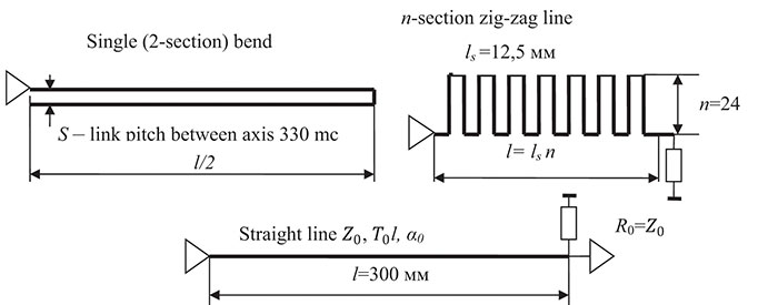
Figure 1. Three topologies of the line having the same length but different delays.
The straight line is shown for comparative quantitative assessment of delays in single and coupled lines.
The proposed graphic-analytical method for simulation assumes the waveforms and parameters of the crosstalk in coupled transmission lines meet the classical definitions (TABLE 1) given in Johnson1 and Barnes3 and illustrated in Table 1.
Table 1. Crosstalk Waveforms and Parameters for the Coupled Transmission Lines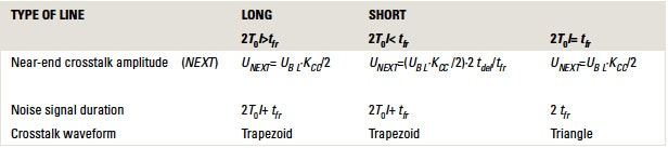
The voltage drop deformation mechanism at the end of a two-section transmission line is detailed in Johnson1. It is based on the summation of the input signal and two backward or near-end crosstalk signals: “precursor” and “post-cursor” in each section of the bend.
If we consider the meander delay line as a train comprising the n two-section bends, a signal generated at the end of each previous bend will be an input signal for each pair of successive sections, and the computation is repeated.
Let’s use the two- and four-section lines to illustrate the step-by-step calculation. The electrically long section case – a delay in one bend (two sections ns = 2) – is greater than the voltage drop rise V at the line input 2ts ≥ tfr (FIGURE 2).
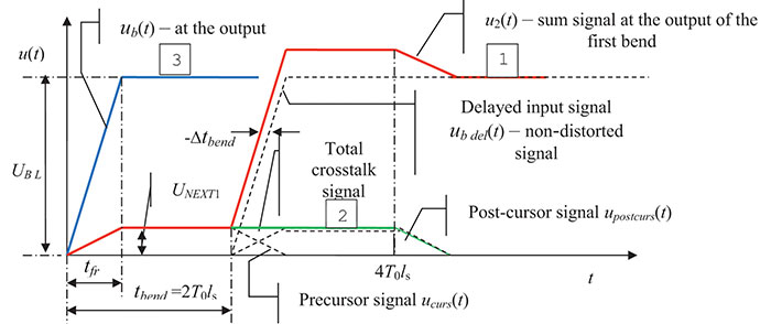
Figure 2. Effect of the near-end crosstalk on the transient process at the end of the first bend (the end of the second section).
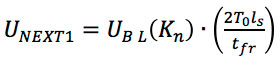
The transient process at the end of a two-section line (ns = 2): as the voltage drop rise increases at the beginning of the meander line, a noise signal-precursor occurs at the output. It is a positive signal with an amplitude of UNEXT1 = UBL * Kn, where Kn = (Kcc + KL) / 4, the front – tfr n= tfr (per Barnes3) and duration – tbend. When the main front passes through the top of the bend, a noise signal – post-cursor – occurs in the next section. This noise signal moves toward the receiver following the main front, and it has the same amplitude and duration. The delayed input signal at the load is summed up with the precursor and post-cursor signals and thus, they form the resulting transient process at the line output.
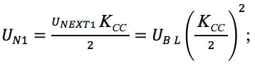
Taking into account UNEXT1 = UBL * KCC / 2, an amplitude of mutual near-end crosstalk in a closed stripline with a uniform dielectric material, where KCC – the capacitive coupling coefficient of the adjacent sections, the analytical expressions for the calculation of each component and the resulting transient process can be represented as follows:
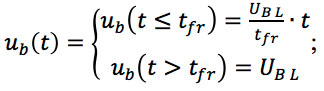
- Input signal
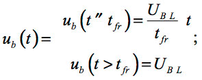 (Eq. 1)
 - Delayed input signal
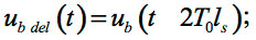
- Precursor signal
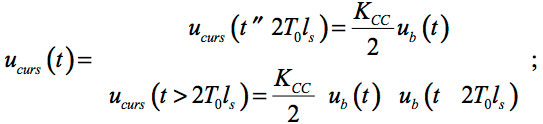
- Post-cursor signal (trapezoid)
Total induced signal is uNEXT1(t) = ucurs(t) + upostcurs(t) (Eq. 2)
The resulting signal of the second section is
uout2(t) = ub del (t) + uNEXT1(t) (Eq. 3)
where
tbend = 2T0ls – the signal delay in one bend on the base
ls – the length of one section
duration of the total induced noise is ![]()
The total crosstalk at the load is summed up with the ideal delayed signal increasing the main front by the value of total induced noise signal. This, in its turn, results in an increase of the main front by the value of –Δtbend π (Figure 2). Thus, the electromagnetic coupling between the sections reduces the efficiency of delay line, and this should be taken into consideration when designing the geometric pattern of bends.
![]() – value of negative delay at the end of the bend is directly proportional to the front (it is evident from the similarity of triangles).
– value of negative delay at the end of the bend is directly proportional to the front (it is evident from the similarity of triangles).
The transient process at the end of a four-section line is (ns = 4).
The signal u2(t) at the outlet of the first bend is an input signal at the inlet of the second bend (FIGURE 3).
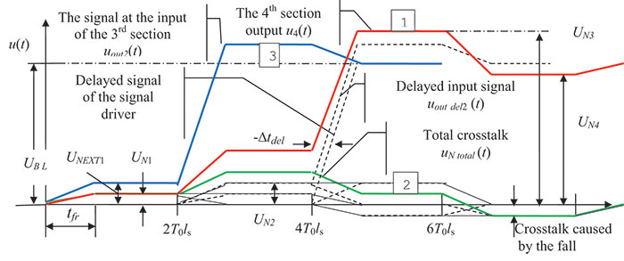
Figure 3. Transient process in a four-section delay line.
The transient process at the inlet of the third section has a rising stepwise shape.
The positive front of each step causes a positive noise in an adjacent section. The negative voltage drop at the 4T0ls section forms a negative noise signal below the ground potential. The total noise at the load is summed with the delayed signal u2 (t) forming the transient process at the outlet of the fourth section u4 (t).
The number of steps is equal to the number of sections: three steps have a positive polarity, and the fourth step has a negative polarity. As the number of bends (m) increases, the amplitude of the primary steps reduces proportionally with the coefficient ![]()
When the main front appears at t = 4T0ls, there is a voltage surge followed by subsequent oscillations around the level of the input signal (UB L). The transient process shows a good agreement with the results of quasi-static analysis using the Computer Simulation Technology (CST) Microwave Studio software described in Barnes3 and Meyer, et al4. The parameters of the transient process are determined as follows:
- input signal of the third section:
uin(t)=uout 3(t);
- delayed input signal:
uin del 3(t) = uout2(t – 2T0ls); (Eq. 4) - amplitude of the first step:
- noise from the first slope up to the end of the front:
un1 (t) = Kn * uNEXT1(t);
- crosstalk caused by the main front: uN2(t) = uNEXT1(t – 2T0ls );
- crosstalk caused by the fall: uN3(t)= –uN1(t – 24ls );
- total crosstalk-signal at the outlet of the fourth section:
uN total(t) = uN1(t) + uN2(t) + uN3(t); (Eq. 5)
- the resulting signal of the fourth section:
uout4(t) = uout del 2(t) + uNtotal(t). (Eq. 6)
Below are three factors the developer needs to take into account while designing the PCB delay lines. Such factors are determined by the electromagnetic coupling between the sections:
- A negative delay value at the outlet of the meander line for topology optimization of the transmission line (–∆tdel);
- A negative surge at the top of the voltage drop (–∆UB L) might cause false actuation of the receiver;
- Prior to the arrival of the front, the rising pulse base lowers the dynamic immunity of the receiver to interference by the value of the total noise uNtotal (t). This reduces the probability of actuation at the estimated time. The noise immunity margin of the element base is no more than 20%.
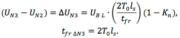
The exact value of negative delay at any predetermined level of the input signal can be calculated using software and solving a system of linear equations (Eq. 4 to 6) for t. From Figure 3 it is seen that the slope of the main front of the signal at the outlet of the last section (segment 4T0ls) differs from the slope of the front at the inlet of the delay line. This is due to the reduction in dynamic amplitude of the third step by the value of crosstalk caused by the main front (UN2). Therefore, the negative delay of the output signal will depend on the voltage level at which it is calculated. Using the following equation, we can calculate the maximum value of the negative delay at a logically significant level of 0.5 from the input signal (FIGURE 4): 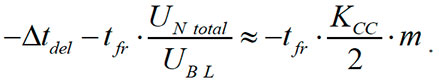
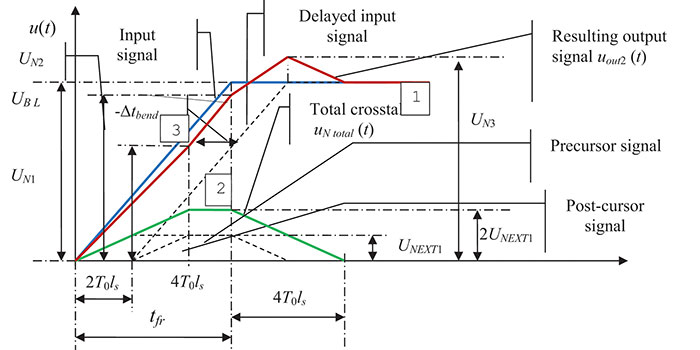
Figure 4. The transient process in a two-section electrically short line.
The negative surge at the pulse peak occurs when the number of bends in the meander delay line is greater than m ≥ 2 (condition for the occurrence of voltage
fall at the pulse peak), and it is:
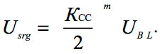
Since the coupling coefficient is always less than one, the negative surge disappears as the number of bends increases.
For the electrically short section case, the delay in one bend (two sections ns = 2) is less than the voltage drop front at the line input 2ts ≥ tfr. The total induced noise differs from the previous case (2ts ≥ tfr) by the doubled amplitude, while the duration is the same. This is due to partial overlapping of the precursor and post-cursor signals. In this case the front of each induced signal is equal to the double trip in one section. Since the front of the input signal (tfr) in this case is greater than the induced noise front duration (tfrNEXT = 2T0ls),3 the amplitude of the precursor and post-cursor signals decreases by a factor of 2T0ls/tfr.
The models of the resulting signal at the line output and its time components are determined as follows:
- Input signal:
- Delayed input signal:
ub del (t) = ub(t – 2T0ls);
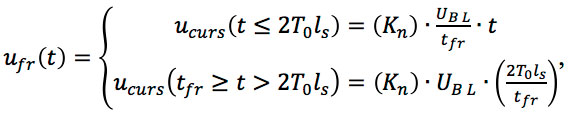
- Amplitude of the precursor and post-cursor signals:
 (Eq. 7)
- Crosstalk under the front:
where Kn = (Kcc /2) in a homogeneous medium;
- Precursor signal:
un(t) = ufr(t) - ufr(t – tf);
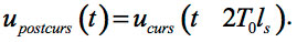
- Post-cursor signal:
upostcurs(t) = ucurs(t – 2T0ls);
- Amplitude of the total induced noise:
Utotal = 2UNEXT1;
- Total noise (the trapezoidal shape):
uN total(t) = ucurs(t) + upostcurs(t); (Eq. 8)
- The resulting signal of the second section:
uout2(t) = ub del(t) + uN total(t); (Eq. 9)
- Total induced noise duration:
τn = 4T0ls + tfr.
Due to the merged precursor and post-cursor crosstalks, the signal front at the output of the bend uout2(t) has three rising segments of different amplitude and duration, as well as the falling voltage drop at the peak.
The transient process at the output of a four-section short line (two bends):
- Input signal of the third section (FIGURE 5)
uin3(t) = uout2(t);
- Delayed input signal
uin del 3(t) = uout2(t – 2T0ls). (Eq. 10)
Figure 5. The transient process in a four-section electrically short line.
Since the signal at the input of the third section (this signal is also the output of the second section) consists of the segments having various steepness and duration (UNn), the induced signal will vary in amplitude and duration.
The amplitude (ΔUN1) and the front of the first bend (tfrN1) in the 0 – 4T0ls section are:
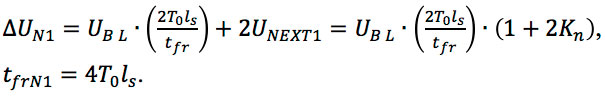
Since the condition 2ts ≥ tfr is met, the crosstalk under the front of the first slope will be:
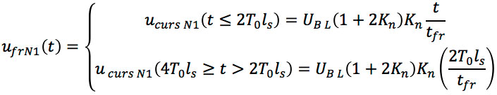
where ![]() in a homogeneous medium;
in a homogeneous medium;
- Precursor noise caused by the first slope:
ucurs N1(t) = ufr N1(t) - ufr N1(t – 4T0ls);
- Post-cursor noise caused by the first slope:
upostcurs N1(t) = ucurs N1(t – 2T0ls);
- Total noise of a triangular shape:
uN total N1(t) = ucurs N1(t) + upostcurs N1(t);
The amplitude and front of the second bend in the 4T0ls – tfr section are:
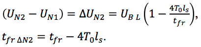
Since the front of the second slope is less than the round trip of the section, the crosstalk under the front will be:
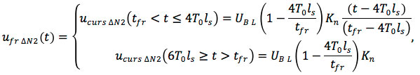
where  in a homogeneous medium;
- Precursor noise caused by the second slope (the main front):

- Post-cursor noise caused by the second slope:

- Total noise (trapezoid):

The amplitude of the third bend in the tfr + 2T0ls section is:
The waveform of the back front:
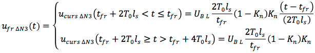
The precursor noise caused by the third slope is:

- Post-cursor noise caused by the third slope:

- Total noise (trapezoid):

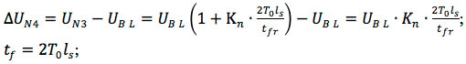
- Crosstalk caused by the fall in the section:
tfr + 4T0ls<t ≤ tfr + 2T0ls;
- Amplitude and duration of the fall:
- Shape of crosstalk caused by the fall:
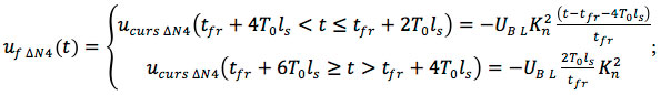
- Precursor noise caused by the fall:

- Post-cursor noise caused by the third slope:

- Total noise (trapezoid):

The summation of noises caused by each bend forms the resulting noise signal utotal(t) at the load, which, when adding the delayed signal uout 2(t), produces the output signal of the fourth section uout 4(t).
The total induced signal at the output of the fourth section is:
uNtotal (t) = uN1 (t) + uN2 (t) + uN3 (t) (Eq. 11)
The resulting signal of the fourth section is:
uout4 (t) = uin del3 (t) + uNtotal (t) (Eq. 12)
The comparison of the 2- and 4-section line models allows us to:
- Develop a general algorithm for building a model of transient processes in the n-section delay lines;
- Evaluate the effect of the step and length of sections on the negative delay value;
- Evaluate the effect of sections that are at a distance from the main front on the signal waveform.
Table 2. Algorithm for Constructing the Transient Process in a Meander Delay Line
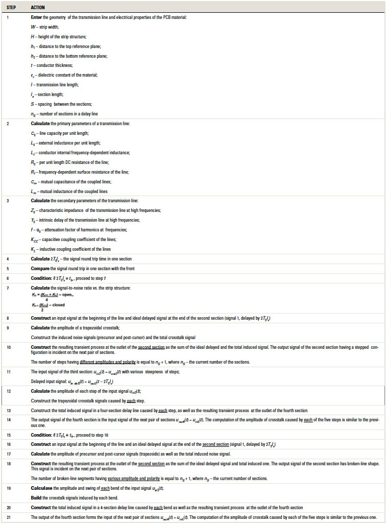
Generalized Algorithm for the Transient Process
This study allows us to make the following conclusions:
- The straight-type delay line occupies minimum space.
- The two-section delay line is not optimum because it does not provide advantageous delay, but it reduces the noise immunity margin.
- With a strong mutual coupling between the sections (>10%), the zig-zag delay line would require the additional sections to compensate the front increase effect when transmitting the data signals. It would be possible to maintain a suitable area under the line, if the pitch between the sections is increased to ensure the coupling coefficient does not exceed 5%.
- The above algorithm allows for determining the parameters of meander delay lines and crosstalk levels.
The results obtained through the simulation of the said method – with consideration of the implementation of the generalized algorithm for constructing the transient process – demonstrate that the accuracy of parameters, including the crosstalk ones, is within five to 10%.
References
1. H. Johnson and M. Graham, High-Speed Signal Propagation – Advanced Black Magic, Prentice Hall, 2005.
2. S.A. Sorokin and S.M. Chudinov, “Electrical and Design Parameters Optimization of Transmission Lines in Computer Systems,” PCD&F, May 2016.
3. John R. Barnes, Electronic System Design: Interference and Noise Control Techniques, Prentice Hall, 1987.
4. C.S. Meyer, D.K. Lynn and D.J. Hamilton, ed., Analysis and Design of Integrated Circuits, McGraw-Hill, 1968.
5. Gazirov T.R., Zabolotsky A.M. and Orlov P.E. “Effect of the Length and Number of Bends on the Delay in Microstrip Meander Line,” Infocommunication Technologies, vol. 12, no. 4, 2014.
is professor and scientific adviser to the general director of NIIVK (Scientific Research Institute of Computer Systems); This email address is being protected from spambots. You need JavaScript enabled to view it.. is chief designer of NIIVK; This email address is being protected from spambots. You need JavaScript enabled to view it..


