Advanced Block Organization in Schematic Design and Layout
Reusing circuits using advanced block hierarchy.
Do you use hierarchy in schematic designs? In layouts? If you think I’m asking if you carry a big stick and issue decrees upon your peers, read this. Many engineers and designers shy away from hierarchy because it’s more complicated, but it only takes a little bit of extra thought to get it right the first few times around. Once designs are using blocks, they become much easier to check and maintain. They also save a lot of design time, mostly the wasted time copying circuitry needlessly. ECOs are also much faster, because one change to the lower level design immediately updates all contexts of the top-level design. There’s no need to change every single one of the repeated circuits.
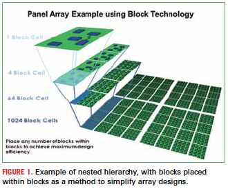
Once traditional hierarchy is in place, more advanced options become available. Many CAE software applications contain the ability to tie a block design directly to a layout block, opening possibilities for organizing both schematic and layout in a more orderly and easy-to-track fashion. This is often referred to as physical hierarchy, and it can be especially useful with design reuse circuits and array types of designs. With array designs, blocks can be organized inside other blocks (Figure 1) in nested hierarchy, making it possible to boil down a very large design into just a few physical blocks to add and maintain.

Last, there is a lesser-known hierarchical capability in some schematic software applications that could be useful. This is the concept of a frame, or a virtual block. This is a block that has no block symbol. It is designated by a border drawn around the circuitry meant to be a block, which is most often tied to a physical block in the layout. This kind of hierarchy is especially useful for smaller schematics; if there is only one page of circuitry representing a board design, it can be broken down into any number of blocks without requiring that the circuits be broken up into separate sheets with one top level design to contain the block symbols. Essentially, the one page of circuitry remains one page instead of three or more. Imagine, for example, a block array design. If there is only one small page of simple circuitry (Figure 1), a virtual block could be drawn around it, and then the block can be assigned a number of placed blocks in the layout, a starting placement value, and an X and Y offset per block for automatic placement of the entire array in the layout. So 1024 block cells would be represented by a one-page schematic.
Traditional block hierarchy. To understand how to use the more advanced types of hierarchy, it helps to examine the commonly used traditional hierarchy. Most readers probably know hierarchy in a schematic design is the process of using “block” symbols to represent a section of circuitry in a design. These symbols represent a separate design from the main, or “top-level,” design, with pins that represent the names of nets that connect from the block design into the main design. Often times, the separate designs are schematics borrowed from previously proved circuits, which are then incorporated into an entirely new design. Blocks are especially useful when the circuitry is repeated over and over in the resulting layout design; this scenario is referred to as replicated hierarchy, meaning that the same block is copied and placed down two or more times.

Use of traditional logical hierarchy opens up more options for completing designs. Portions of designs can be divided up among a team of engineers, with the main or “host” design ultimately owning the finished copy of each person’s work. These design portions can be sent off for simulation or testing without requiring the entire design to be sent off, permitting progress to continue in other areas of the design. Dividing designs into blocks can also help floor-planning for the layout, where specific functional areas of the layout are grouped logically.
But the most obvious advantage of using blocks is seen with replicated hierarchy. When a block symbol is placed two or more times in a schematic, there is still only one underlying schematic. The schematic application takes care of displaying each block’s “context,” which holds unique references and property values for every component. So while there is one underlying schematic, the same component viewed through one block has the same number of references as there are uniquely placed blocks.
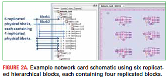
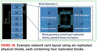
Physical block hierarchy. Building on the concept of logical hierarchy is physical hierarchy. Once a schematic is defined using hierarchical blocks, those blocks can then be assigned directly to a block in the layout. The various CAD systems handle this concept differently, with some having actual block geometries in the layout and others simply defining the physical “block” area using attributes or properties. This method is helpful for layouts with replicated blocks, because once the layout block is created, it can easily be placed again and again. The creation and editing of the layout circuits is much simpler, because changes to the replicated block are made at the block level, which removes the need to make repetitive changes across all copies of the block.

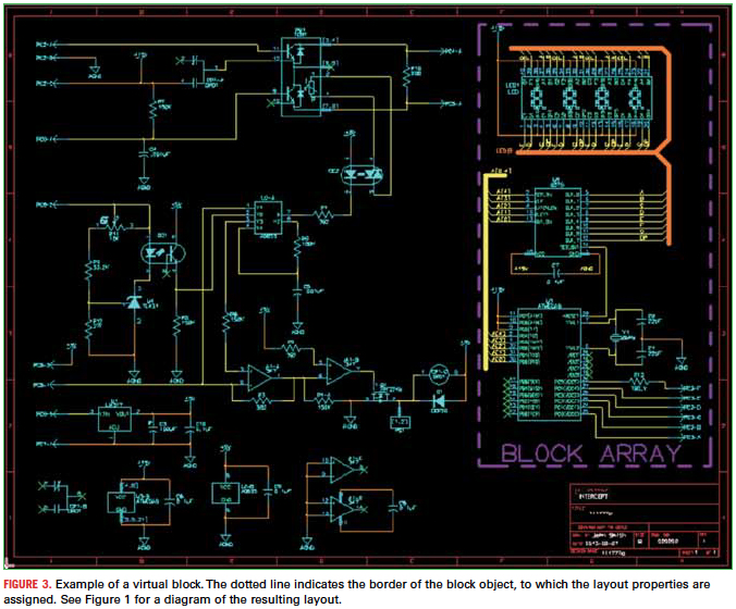
Virtual blocks. Building on the concept of physical hierarchy is a whole new level, the virtual block, or frame. As an example, imagine a simple design with only one page of circuitry. But this circuit is placed into an array design 1024 times. Using the other forms of hierarchy, this would require 1024 block symbols to represent the one page. With a virtual block, however, this can be programmed directly on the schematic page. Figure 3 depicts an example of a block array schematic. The circuitry to the left is the main level circuitry, while the shaded box indicates the virtual block. This block is defined with properties specifying the number of times it is placed, and the X and Y offsets for each block. Viewing a block context is the same as though the virtual block were a block symbol.
[Ed.: To enlarge the figure, right-click on it, then click View Image, then left-click on the figure.]

The virtual block can be used for many kinds of designs, but another good example is a hybrid design with separate circuits for the cavities in the design. The wirebonds for a chip, for example, would be represented on the schematic with a virtual block surrounding the chip. The block would have virtual block pins at the location where the net crosses the block boundary. These pins create a split in the net that is exactly the same as a split in a net across traditional hierarchy, but without requiring the manually defined block pin. This permits the nets from the pins on the chip to traverse up to the main level design, but in this case, the hierarchy is all on the same page. This result of using virtual blocks tends to be a much simpler schematic design, but it also ensures greater design integrity in the layout since it is conceptually easier to track the connections of the design.
In summary, the use of any flavor or hierarchy almost always serves to reduce complexity, speed design cycle time, ease ECOs, and increase opportunity for design reuse. While the concept of hierarchy is more complex, the resulting design is not. Be sure to weigh these options before beginning a new design, because once the plan is laid, it can become much easier to accomplish the task.
Abby Monaco, CID, is product and marketing manager for Intercept Techology (intercept.com); This email address is being protected from spambots. You need JavaScript enabled to view it..


